文章信息
- 廖楠, 崔小欣, 廖凯, 王田, 于敦山, 程玉芳
- LIAO Nan, CUI Xiaoxin, LIAO Kai, WANG Tian, YU Dunshan, CHENG Yufang
- 一种针对FPGA密码模块的非侵入式故障攻击
- A Non-invasive Fault Attack on FPGA-based Cryptographic Applications
- 北京大学学报(自然科学版), 2016, 52(2): 193-198
- Acta Scientiarum Naturalium Universitatis Pekinensis, 2016, 52(2): 193-198
-
文章历史
- 收稿日期: 2014-12-18
- 修回日期: 2015-03-19
- 网络出版日期: 2016-02-11
2. 国民技术股份有限公司, 深圳 518057
2. Nationz technologies Inc, Shenzhen 518057
Nowadays FPGA has become a significant device in finance, communication and military fields due to its flexibility and performance advantages. Since the data security is one of the most important issues in these sensitive fields, an increasing attention has been paid to the FPGA security research[1]. In the modern FPGA design, strict cryptographic algorithms are applied to provide closed reliable computing environ-ments for the sensitive information. However, as the development of physical attacks, mathematical algorithms alone cannot guarantee the security of FPGA device. Under the physical attacks, sensitive information which is correlated to the secret key will leak. Thus the attacker can recover the secret key and break into the cryptosystem. Attacks that target straightly the physical implementations of FPGA-based cryptographic applications have become the main threat in recent years.
Now, side channel attacks (SCA) are the most popular attacks aiming directly at the FPGA device[2]. Power consumption, timing information and electro-magnetic leaks are usually utilized as side channel information to disclose the encryption keys. However more and more countermeasures based on software and hardware have been proposed to resist SCA. Thus some new methods like fault attack and template attack are introduced. Among these methods, fault attack, which was first presented in 1997, has become a powerful and popular attack against cryptographic systems[3].
Fault attack works by inducing faults to alter either the control flow or the internal-state data of the cryptographic algorithm implemented on the target device. Based on the fault model, the attacker can acquire sufficient information from the faulty ciphertexts to retrieve the secret key. Fault attacks have been successfully employed to attack all kinds of cryptographic algorithm like the AES, DES, ECC and RSA respectively, even if the cryptographic system is mathematically secure and endowed with counter-measures against SCA.
Several techniques have been proposed to inject faults into the hardware implementation, i.e. the clock frequency variation, the temperature variation and the irradiation by a laser beam. However these methods are either hard to control the variable precisely or too complicated and high-cost. Moreover some methods will cause unrecoverable damage to the device. In this paper, a non-invasive, high-efficient and low-cost technique is proposed to inject faults into the FPGA device by lowering its supply voltage. This method is successfully employed on a FPGA board designed with countermeasures against physical attacks. Using a power supply and a personal computer, the full 128-bit key of AES is retrieved correctly by 8 pairs of correct and faulty ciphertexts within a few minutes.
1 Fault Injection TechniqueFor a logic circuit, it needs a setup time for the logic gates to switch into a stable state. Raising the clock frequency or lowering the supply voltage may make some logic paths fail to setup properly[4]. Based on this principle, the proposed technique injects faults by lowering the supply voltage while keeping the clock frequency fixed. By gradually lowering the supply voltage, the longest critical path will fail first, thus the device will output faulty results. More setup failures will appear if the voltage continues to decline. However if the voltage drops down to a certain point, the setup failures will be substituted by functional errors, which may make the device stop working. Thus the exploitable voltage range starts from the point the longest critical path fails the first time to the point functional errors appear. It can clearly been seen that finding out the critical path of cryptographic algorithm implementation is critical to the attack under the fault injection technique.
AES is chosen as the target cryptographic algorithm to implement the attack in this paper. AES is an iterated block cipher that can encrypt 128-bit wide plaintext blocks using a 128-bit, 192-bit or 256-bit key[5]. Without loss of generality, this paper focuses on the 128-bit key size version AES. The AES cipher is based on a ten-round iteration which is applied to the 16 bytes data block to be encrypted. A fixed sequence of operations is consisted in each round: SubBytes, ShiftRows, MixColumns and Add-RoundKey. The only exception to the repetition is the last round of encryption where the MixColumns is missing and an extra AddRoundKey performed before the first round.
Obviously, the four operations are the most important part of the encryption process, which compose the critical path of the AES. When the supply voltage is lowered in the exploitable voltage range, setup failures will appear in the encryption round, influencing the 16 bytes internal-state data. Since the implementation has an 8-bit data path, the fault type will be “byte-flip”. Besides, the stress caused by the insufficient supply voltage remains gentle, dysfunc-tions will not appear suddenly and thus single faults that most fault models are based on will appear at a high probability. As for the fault location, because the critical path is highly data-dependent and each round which the same operations, it can be predicted that the faults will appear randomly in each round. Therefore the attacker can pick out the exploitable ones according to the fault model.
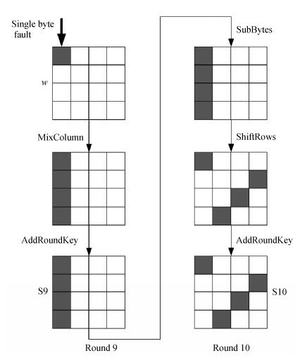
2 Fault ModelAccording to the fault injection technique and the AES algorithm, single byte model which aims at the 16 bytes inner-state data will be considered. By comparing multifarious models in literature, the fault model proposed by Dusart et al.[6] seems to be the most suitable one in this research. Dusart et al. proposed the differential fault analysis on AES, which is based on the single byte fault injection between the MixColumns step in the eighth round and that in the ninth round, as shown in Fig. 1. Since the last round doesn’t have MixColumns step, the fault only influences 4 of the 16 bytes output ciphertext. Furthermore, it is worth nothing that the 4 bytes’ location is decided by the fault position. If the single-byte fault position is in the first column of the state w like Fig. 1, the faulty bytes in the ciphertext will be
|
| Figure 1. Single byte fault propagation in AES |
Analyzing the fault propagation in Fig. 1, the operation of ShiftRows, MixColumns and SubBytes are fixed, and only the last round key affects the output ciphertext, thus the attacker can make a hypothesis on the 4 bytes round key in the analysis. Define the state before the MixColumns in round 9 as w. Since the attack only care about the difference between the correct w and the faulty one, and the operations from w to S10 are all linear except the SubBytes in round 10. Therefore the effect of AddRoundKey in round 9 can be bypassed. When a pair of correct and faulty ciphertexts is obtained, the attacker inverts the ciphertexts to the states w and
| $ $\begin{array}{l} \delta = w \oplus \bar w\\ \;\;\; = {\rm{InvMixcolumn(K9}} \oplus {\rm{S}}9{\rm{)}} \oplus {\rm{InvMixcolumn(K9}} \oplus {\rm{\tilde S}}9{\rm{),}}\\ \;\;\;{\rm{ = nvMixcolumn(S9}} \oplus {\rm{\tilde S}}9{\rm{),}} \end{array}$ $ | (11) |
| $ $\begin{array}{l} {\rm{S}}9 = {\rm{InvSubBytes}}({\rm{InvShiftRows(K10}} \oplus {\rm{S}}10{\rm{)}}),\\ {\rm{\tilde S}}9 = {\rm{InvSubBytes(InvShiftRows(K10}} \oplus {\rm{\tilde S}}10{\rm{))}}{\rm{。}} \end{array}$ $ |
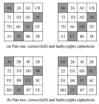
Based on the analysis in the last section, the fault injected is most likely a single byte fault. Therefore the attacker can check if the obtained difference δ is composed of a single byte. Depending on whether the difference is only a single byte or not, the attacker can decide if the 4 bytes round key hypothesis is a valid one or not. For one pair of correct and faulty ciphertexts, there can be hundreds of valid candidates, however with two pairs which have the same fault locations, the corresponding 4 bytes round key can be uniquely determined with a reasonably high proba-bility. Thus the complete last round key can be recovered with 8 pairs of correct and faulty cipher-texts.
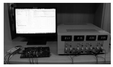
3 Attack Experiments 3.1 Target platformThe attack target is a FPGA board specifically designed to secure the cryptographic applications against physical attacks, which contains a crypto-graphic FPGA Virtex-XC5VLX110 and a control FPGA Virtex2Pro-XC2V1000. The standard AES algorithm is implemented in the cryptographic FPGA and the control FPGA is responsible for sending and receiving data. Thus the low voltage attack will be carried out on the cryptographic FPGA. The cryptographic FPGA operates correctly at a frequency of 50 MHz with a nominal supply voltage of 1 V. In the experiment, the cryptographic FPGA is fed by a power supply with appropriate precision and the voltage measures are taken with a multimeter with a precision of 1 mV. The data transmission is realized by a USB cable connecting the FPGA and the computer. All the data processing is realized on the PC. The experiment platform is shown in Fig. 2.
|
| Figure 2. Experiment platform |
3.2 Experiment results
The exploitable voltage range should be found out first. Slowly lowering the supply voltage, it can be observed that the circuit starts to output faulty ciphertexts for a voltage of about 835 mV and beneath. By continually lowering the voltage to about 785 mV, the target circuit stops working, which indicates that functional errors appear. Therefore the exploitable voltage ranges from the 785 mV to 835 mV.
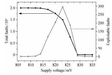
To further investigate the characteristics of faults, we chose several intermediate voltages within the exploitable voltage range to implement the attack. For the effectivity and consistency of comparison, twenty thousand different plaintexts and one key are prepared. For each voltage level, these plaintexts are encrypted by the same key, and the twenty thousand ciphertexts are recorded. By comparing the ciphertext with the corresponding correct one, we can know whether the result is faulty. Since the fault model is based on the single fault between the MixColumns step in the eighth round and the MixColumns step in the ninth round, we can further find out the exploitable faults as presented in last section. The number of the total faults and the exploitable ones at each voltage are depicted in Fig. 3. As shown in the figure, the FPGA moves from an error-free state to a fully faulty behavior within about 25 mV. However the exploitable faults do not show the same trend, its distribution is like a bell shape. From the voltage of 829 mV, the number of exploitable faults has a sharp increase as the voltage decrease and reaches the maximum of 296 at about 823 mV. Continue lowering the voltage, the exploitable faults also reduce quickly, for instance, the number at 814 mV is only 15. When the voltage is lowered beneath 812 mV, the exploitable faults do not appear any more. The phenomenon may be owing to the fact that multiple critical paths are violated by faults when the voltage is beneath 812 mV. Therefore the appropriate supply voltage should be set between 814 mV and 823 mV when implementing the attack.
|
| Figure 3. Number of total faults and exploitable faults |
Based on the analysis above, the supply voltage is set at 826 mV. At this voltage, 7622 total faults including 187 exploitable faults are obtained. For further classification, all the fault situations, namely
|
| Figure 4. Two pairs of correct and faulty ciphertexts |
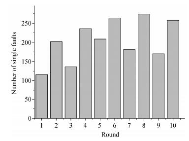
For further consideration, the distribution of single faults in each round is investigated. It is done by inverting the faulty ciphertexts with the known key and calculating the difference between each state of the faulty and the correct ones. The round at which the single bye difference appears is considered to be the round injected by single fault. The data at the supply voltage of 826 mV is selected. Fig. 5 depicts the result of distribution. 2046 single faults of 7622 total faults spread uniformly at all the ten rounds, which can prove that single byte fault models based on other specific rounds apply to this injection technique too. It can be predicted that combining different fault models can improve the attack efficiency, which will be our direction of further research.
|
| Figure 5. Distribution of single faults in each round |
4 Conclusion
A non-invasive, high-efficient and low-cost fault attack on FPGA-based cryptographic applications is proposed in this paper. By lowering the supply voltage of FPGA device, the setup failures appear in the critical path of implementation, which leads to faulty ciphertexts. Based on appropriate fault model, the encryption key can be retrieved easily. Attack experiments show that the full 128-bit key of AES is retrieved correctly by only 8 pairs of correct and faulty ciphertexts within a few minutes with the help of a power supply and a personal computer.
| [1] | Wollinger T, Paar C. Security aspects of FPGAs in cryptographic applications // new algorithms, archi-tectures and applications for reconfigurable com-puting. Cambridge, MA: Springer, 2005: 265-278 |
| [2] | Hori Y, Katashita T, Sasaki A, et al. Sasebo-giii: a hardware security evaluation board equipped with a 28-nm FPGA // Consumer Electronics (GCCE), 2012 IEEE 1st Global Conference on. Tsukub, 2012: 657-660 |
| [3] | Boneh D, DeMillo R A, Lipton R J. On the importance of checking cryptographic protocols for faults // Advances in Cryptology -EUROCRYPT'97. Berlin: Springer, 1997: 37-51 |
| [4] | Barenghi A, Bertoni G, Parrinello E, et al. Low voltage fault attacks on the RSA cryptosystem // Fault Diagnosis and Tolerance in Cryptography (FDTC), 2009 Workshop on. Lausanne, 2009: 23-31 |
| [5] | Daemen J, Rijmen V. The design of Rijndael: AES-the advanced encryption standard. Berlin: Springer, 2002 . |
| [6] | Dusart P, Letourneux G, Vivolo O. Differential fault analysis on AES // applied cryptography and network security. Berlin: Springer, 2003: 293-306 |
 2016, Vol. 52


